jvc 7 inch touch screen car stereo
jvc 7 inch touch screen car stereo.CD74AC164M is an 8-bit serial input parallel output shift latch. The microprocessor controls the clock and data input of the shift latch through the IO port. Scan microprocessor IO port the CD74AC164M an MR pin is asserted high, the output pin will automatically CD74AC164M: Q0 is set to high, and then fed to a clock signal: CP, the clock signal rising period shift bit latch automatically the data Q0 is written to Q1 and saved . When the rising edge of the next clock pulse arrives, the data of Q1 is written to Q2 and Q1 is automatically cleared, and the others are performed in sequence. The written pulse is continuously shifted with the rising edge of the shift clock until it is shifted out from the output. Using this feature of the shift latch, the pulse can be moved to the transmitting tube on the rising edge of the shift clock, and the transmitting tube is lit. The output end of the first shift latch is connected to the input end of the next stage, and the written pulse can be shifted to the next stage. Therefore, through the cascade of shift latches, the microprocessor can drive more transmitters. Combining these features i.e. may be transmitted by one lighting tube. The above is only a principle introduction to the transmitting end. The actual circuit is driven by a level of current and voltage behind the displacement latch.ICs, for example: Maxwell ??s constant current drive ICs: MAX6966, TI ??s ULN2803A, etc., because the scan signal current output by the displacement latch is too small to drive the infrared emitting diode, a level one current and voltage drive IC must be added behind . The driving circuit is shown in the following figure:
IQTouch K Interactive Display
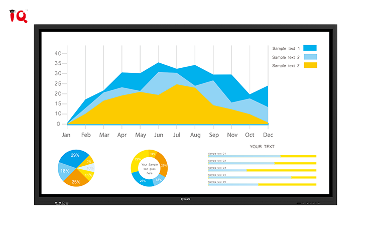
jvc 7 inch touch screen car stereo.CD74AC164M is an 8-bit serial input parallel output shift latch. The microprocessor controls the clock and data input of the shift latch through the IO port. Scan microprocessor IO port the CD74AC164M an MR pin is asserted high, the output pin will automatically CD74AC164M: Q0 is set to high, and then fed to a clock signal: CP, the clock signal rising period shift bit latch automatically the data Q0 is written to Q1 and saved . When the rising edge of the next clock pulse arrives, the data of Q1 is written to Q2 and Q1 is automatically cleared, and the others are performed in sequence. The written pulse is continuously shifted with the rising edge of the shift clock until it is shifted out from the output. Using this feature of the shift latch, the pulse can be moved to the transmitting tube on the rising edge of the shift clock, and the transmitting tube is lit. The output end of the first shift latch is connected to the input end of the next stage, and the written pulse can be shifted to the next stage. Therefore, through the cascade of shift latches, the microprocessor can drive more transmitters. Combining these features i.e. may be transmitted by one lighting tube. The above is only a principle introduction to the transmitting end. The actual circuit is driven by a level of current and voltage behind the displacement latch.ICs, for example: Maxwell ??s constant current drive ICs: MAX6966, TI ??s ULN2803A, etc., because the scan signal current output by the displacement latch is too small to drive the infrared emitting diode, a level one current and voltage drive IC must be added behind . The driving circuit is shown in the following figure: IQTouch K interactive touch screen feature 20-point touch and dual system -- Android 8.0 system and optional OPS Windows 10Pro system. Its 4K UHD resolution facilitates presentations and collaboration. With optional multi-screen casting software, IQClass 6.0 and installation-free IQClass Plus software, IQTouch K Series can help create an interactive and collaborative teaching atmosphere in class.
Let’s See IQTouch K Interactive Display
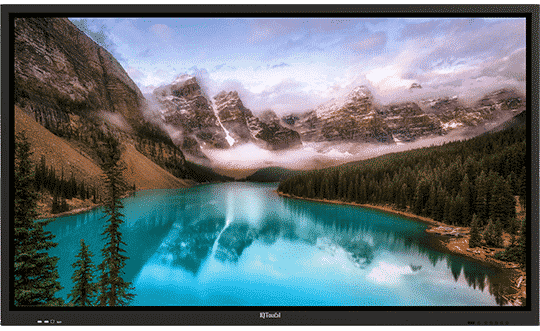
4K UHD Display
Stunning 4K UHD can display a cystal clear image on
screen.
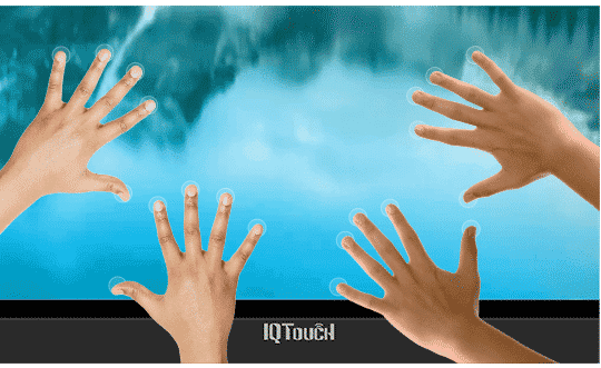
20 Touch Points
Enable an interactive and collaborative teaching atmosphere
in classroom.
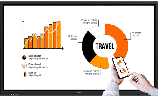
Built in Wifi hotspot & Optional
Multi-screen casting Software
Support to cast your devices to the screen wirelessly,
and your devices can control the screen wirelessly.
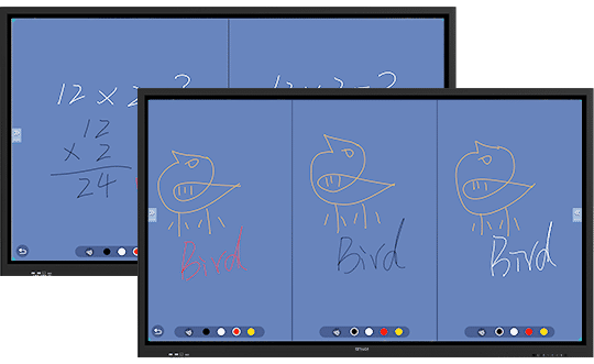
Easy-to-Use Built-in Whiteboard
Software
Built-in Whiteboard software under Android system allow to do
two separate screen teaching and three separate screen teaching.
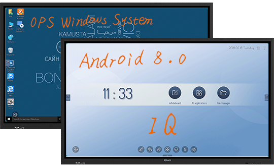
All-channel Annotation
Enable to annotate under Android system and
Windows system.
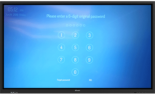
Power On/Off Lock and Screen Lock can
be Set with A Password Respectively
Support to lock screen and lock power on/off button
to avoid student
malfunction and secure privacy.
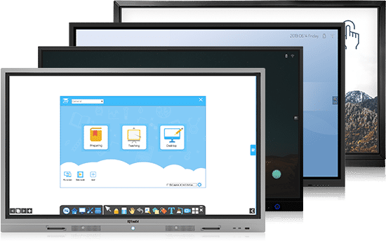
To compare with our other IQTouch Series
RESOURCE FOR YOU
Resource for you
Product Tag
Send us a message
Get in touch
-
![icon-phone]() +86-591-38202660
+86-591-38202660
-
![icon-mob]() +86-15280405902
+86-15280405902
-
![icon-mail]() iqboard@iqboard.net
iqboard@iqboard.net
-
![icon-addr]() 6th Bldg. High-Tech Base.
6th Bldg. High-Tech Base.
Fuzhou FuJian Prov. China
Solutions
Copyright © 2017.Returnstar Interactive Technology Group Co., Ltd All rights reserved.

